Session I
In the first week of Physical Computing, we looked at the basics of the Arduino and the Grove Kit to program simply instructions, like with the built-in LED, and then an external one wired in to the breadboard. A big benefit is that th Arduino doesn’t need to be plugged in to computer once the code has been put on to it, so more useful than the Makey-Makey. We then used the LCD screen to display text.
Grove - Starter Kit v3 [link]
Sensors Overview
Bread board
Power rails work up-down.
Lettered connections work left-right.
Tutorial codes:
/*
Blink
Turns an LED on for one second, then off for one second, repeatedly.
Most Arduinos have an on-board LED you can control. On the UNO, MEGA and ZERO
it is attached to digital pin 13, on MKR1000 on pin 6. LED_BUILTIN is set to
the correct LED pin independent of which board is used.
If you want to know what pin the on-board LED is connected to on your Arduino
model, check the Technical Specs of your board at:
https://www.arduino.cc/en/Main/Products
modified 8 May 2014
by Scott Fitzgerald
modified 2 Sep 2016
by Arturo Guadalupi
modified 8 Sep 2016
by Colby Newman
This example code is in the public domain.
https://www.arduino.cc/en/Tutorial/BuiltInExamples/Blink
*/
// the setup function runs once when you press reset or power the board
void setup() {
// initialize digital pin LED_BUILTIN as an output.
pinMode(LED_BUILTIN, OUTPUT);
}
// the loop function runs over and over again forever
void loop() {
digitalWrite(LED_BUILTIN, HIGH); // turn the LED on (HIGH is the voltage level)
delay(1000); // wait for a second
digitalWrite(LED_BUILTIN, LOW); // turn the LED off by making the voltage LOW
delay(1000); // wait for a second
}
//Hello world!!
#include <Wire.h> // I2C library for LCD
#include <rgb_lcd.h> // Grove LCD library
const int pinButton = 3; // Pin for the button
const int pinLed = 7; // Pin for the LED
rgb_lcd lcd; // Create an LCD object
void setup()
{
pinMode(pinButton, INPUT); // Set button pin as input
pinMode(pinLed, OUTPUT); // Set LED pin as output
lcd.begin(16, 2); // Initialize LCD with 16 columns and 2 rows
lcd.setRGB(0, 255, 0); // Set LCD backlight color to green
lcd.print("Press Button!"); // Display message on LCD
}
void loop()
{
// Check if the button is pressed
if(digitalRead(pinButton))
{
// When button is pressed, light up LED
digitalWrite(pinLed, HIGH);
// Update the LCD to display "Hello World!"
lcd.clear();
lcd.setCursor(0, 0); // Move cursor to the top left
lcd.print("hello world!"); // Display "Hello World!"
}
else
{
// Turn off the LED when the button is not pressed
digitalWrite(pinLed, LOW);
// Update the LCD to display "Press Button!"
lcd.clear();
lcd.setCursor(0, 0); // Move cursor to the top left
lcd.print("Press Button!"); // Display "Press Button!"
}
delay(10); // Short delay to avoid excessive polling
}
Session II
This week we tried our own programming more, with the components from the Arduino Grove Starter Kit. This was one of the ones I did:
Siren with surprise text:
#include <Wire.h>
#include "rgb_lcd.h"
rgb_lcd lcd;
// const int colorR = 0;
// const int colorG = 0;
// const int colorB = 255;
void setup()
{
// set up the LCD's number of columns and rows:
lcd.begin(16, 2);
// Print a message to the LCD.
lcd.print("");
delay(1000);
}
void loop()
{
// set the cursor to column 0, line 1
// (note: line 1 is the second row, since counting begins with 0):
lcd.setCursor(0, 1);
// print the number of seconds since reset:
lcd.print(" ");
lcd.setCursor(0, 0);
// print the number of seconds since reset:
lcd.print("weeee");
lcd.setRGB(255, 0, 0);
delay(1500);
lcd.setCursor(0, 0);
// print the number of seconds since reset:
lcd.print(" ");
lcd.setCursor(0, 1);
// print the number of seconds since reset:
lcd.print("woooo ");
lcd.setRGB(0, 0, 255);
delay(1500);
lcd.setCursor(0, 1);
// print the number of seconds since reset:
lcd.print(" ");
lcd.setCursor(0, 0);
// print the number of seconds since reset:
lcd.print("weeee");
lcd.setRGB(255, 0, 0);
delay(1500);
lcd.setCursor(0, 0);
// print the number of seconds since reset:
lcd.print(" ");
lcd.setCursor(0, 1);
// print the number of seconds since reset:
lcd.print("woooo");
lcd.setRGB(0, 0, 255);
delay(1500);
lcd.print(" ");
lcd.setCursor(0, 1);
// print the number of seconds since reset:
lcd.print("(surprise text)");
lcd.setRGB(0, 0, 0);
delay(500);
lcd.setCursor(0, 1);
lcd.print(" ");
}
I changed the code to vary the colours and the text on the LCD screen.
The next, and slightly more 'physical' aspect of Physical Computing was with MadMapper. We went to the Blue Shed for this tutorial, which my group all really enjoyed. We set up plinths in one of the rooms and started with block colors to position each of the frames that we wanted, and then replaced it with various clips (and a TikTok Anne blackmailed us into doing, lol) to trial projection mapping.
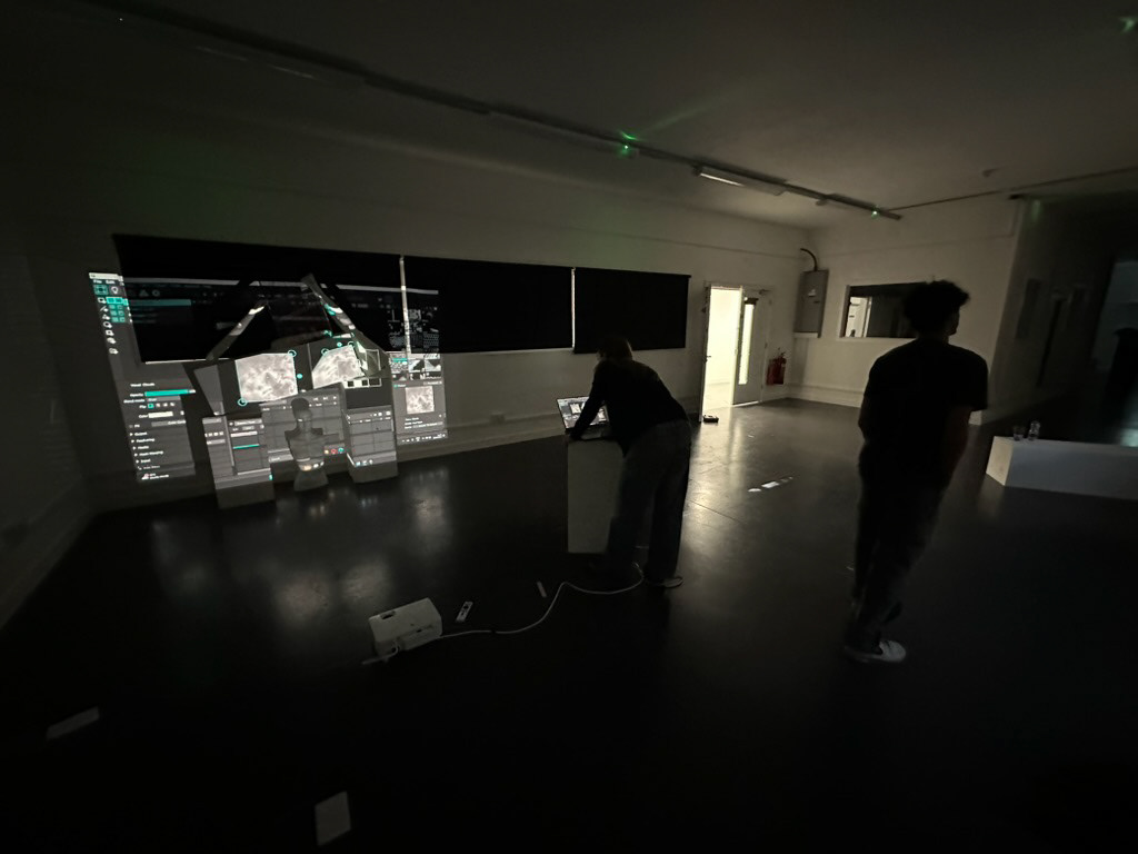
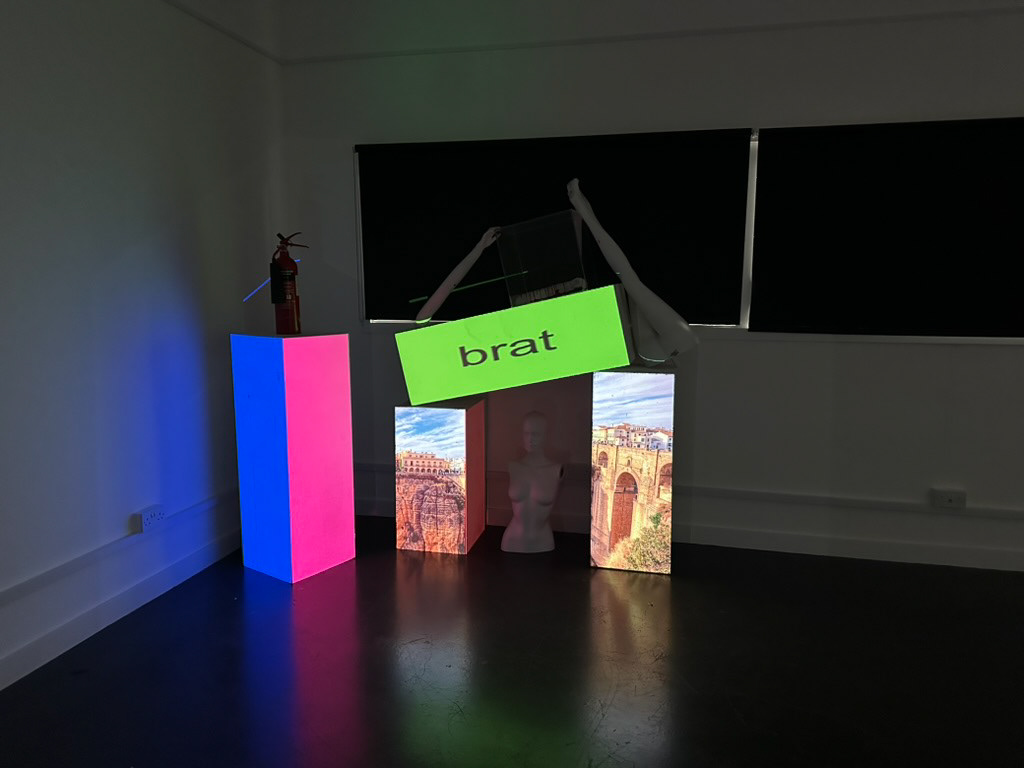
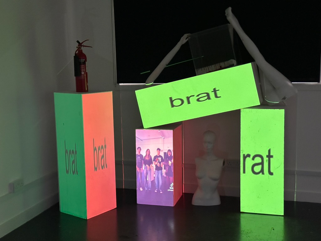
I am likely as embarrassed about the content projected as you are reading this, but it was an interesting proof of concept, and we decided to use projection mapping to display the elements for our more 'final' work.
As a comedic side note, this was also the day me and Peter were asked to leave the gym as he was wearing Tims and not trainers:
